Understanding the Testing Standards
What is behind a listing? We know the components are tested, but to what degree? This information can help if an Authority Having Jurisdiction (AHJ) is questioning the loading of an application using a listed support or brace. This article will provide some background of what the components go through for listing and provide an overview of two different Underwriter Laboratories (UL) testing standards: UL 203, Pipe Hanger Equipment for Fire Protection Service for Fire Protection System Supports, and UL 203A, Sway Brace Devices for Sprinkler System Piping for Seismic Applications.
Since UL is generating testing standards, it’s important that the testing standards are credible. It needs to be mentioned that UL doesn’t generate the standards on their own. The standards also have Standards Technical Panels (STPs) consist- ing of manufacturers and other fire protection industry representatives. The STPs serve as the consensus body for both American National Standards (ANS) and National Standards of Canada (NSC). The American National Standards Institute (ANSI) accredits the UL testing standards in the USA. For Canada, this is accredited by the Standards Council of Canada (SCC) and enables UL to develop documents for the National Standards of Canada (NSCs).
UL 203 will be covered first. Its scope addresses the performance of pipe hangers for use in supporting sprinkler systems, water-spray systems, and other piping used for protection. Similar to Chapter 9 of NFPA 13, Standard for the Installation of Sprinkler Systems, the UL standards do not cover products fabricated from iron or steel rods such as U-type hangers, hanger rods, and coach screw rods. The minimum hanger rod sizes in the standard align with the requirements of Chapter 9 of NFPA 13.
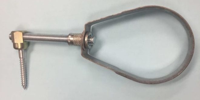
The components that make up the hangers have to be made of ferrous materials. (See Figure 1.) As such, there are no burn tests applied to these components. There is an exception for nonferrous materials, such as plastics, where further evaluation would be required for exposure to fire and aging. The thickness of the iron or steel has to be at least 3/16 in. An exception is when a protective coating is applied. The other exceptions to the minimum thickness are retaining straps, clevis-type hangers or other flat iron hangers from steel at least 1/8-in. thick, C-clamps that meet other UL criteria, and pressed-steel concrete inserts at least 1/8-in. thick. When the metallic coating is applied to the component, the coating goes through a thickness test. Acid is mixed with distilled water and a water droplet is applied at a rate of 100 (+5) drops per minute. Each sample is subjected to three or more points on the component. The test is run until there is a first appearance of the base metal shown by a change of color. A thickness of coating factor is applied and multiplied by the time in seconds required to expose the base metal.
The hanger has to support a load so a pull test is applied. The weight of metallic pipe is calculated for a span of 15 ft and multiplied by 5 and a fixed load 250 pounds-force (lb-f ) is added. The alternative is to apply a table within the testing standard of the pull test loads for metallic pipe. The minimum load for a hanger is 750 lb-f starting at the 3/4-in. nominal pipe size. The loads increase up to 7900 lb-f for larger pipe sizes to 12-in. nominal pipe size. Thermoplastic pipe has lesser loads for hangers where the weight is calculated for the maximum span of water-filled plastic pipe multiplied by 5 plus a fixed load 250 lbs-f that is applied. A table is also provided for plastic pipe as an alternative for the pull test load requirements. The table starts with 1/2-in. nominal pipe size with a load of 340 lb-f up to 4-in. nominal pipe size with a load of 750 lb-f. Riser clamps are also included in this test where the riser clamp is tightened to the torque value indicated by the manufacturer. This ensures that when a listed hanger is used for the appropriate pipe size, the hanger will support the load. When selecting a listed component, one applies just the weight of the water filled pipe to the listed value. There is no need to calculate five times the weight of the water-filled pipe or the 250-lb increase when applying a listed hanger since that is already included in the listing process.
Concrete inserts, expansion anchors, and powder-driven anchors are also included in this testing standard. The setup for the concrete inserts closely duplicates the intended installation in the field in concrete blocks. This standard includes how to prepare the concrete blocks where it’s cured for 28 days. The pull test has the test loads per the table for metallic pipe as described above. The load is applied for one minute without rupture, pull out, or release of the load.
The expansion anchors are installed per the manufacturer’s instructions into cured concrete blocks. The load is increased until the required loading is achieved for the anchor. Other fasteners, including powder-driven studs, are installed into cured concrete blocks or steel. Welding studs are welded to not less than 3/16-in. steel plates per the manufacturers instructions. C-clamps are tested in each possible position to address any installation orientation and a different sample is used for each test. The loading for these fasteners and attachments are also applied per the table in the testing standard for metallic pipe. Prior to the pull test, the fasteners and hangers are also subjected to a vibration test for 100 hours.
An upward thrust test is completed for pipe hangers, surge clips, or other surge accessories. The devices intended to restrain vertical movement have to withstand a force of 340 lbs without a displacement of more than 1/8 in. These devices also go through a tension- compression test apparatus that mimics their intended installation. (See Figures 2 and 3.) That sums up the testing of hangers.
Next we’ll look at the UL 203A standard for sway brace devices for sprinkler system piping. The scope covers sway brace devices for fire protection piping in locations subject to earthquakes. The braces include rigid sway braces that are intended for resisting both tension and compression loads and non-rigid sway braces intended for resisting loads in tension only. This standard also includes restraint devices to restrict the movement of the pipe.
The sway brace fitting or structural attachment fitting is made from flat iron or steel and the thickness of the metal shall be at least 7 gauge (3/16 or 0.1875 in.). The exception, similar to the hanger requirements, is when protective coatings are applied such as a zinc coating, hot-dipped galvanized or zinc-iron alloy-coated or galvannealed. Other finishes are permitted when it provides corrosion protection equivalent to the coating indicated in the previous sentence. Cables are zinc coated in accordance with an ASTM standard or equivalent corrosion resistant coating or material.
Rigid sway bracing goes through a load test as installed per the manufacturer’s installation instructions. This will duplicate their intended field installation. The load applied will be 1.5 times the manufacturers load rating or the load rating specified by the Minimum Rate Load table within the standard, whichever is greater. The load is held for one minute on both tension and compression without excess movement. The movement permit- ted is split between pipes less than 4 in. where 1 in. horizontal movement is allowed and pipe sizes greater than or equal to 4 in. allows up to 2 in. of horizontal movement. The test angles in degrees range from 30 to 90 where the maximum movement is specified at each test angle. This ranges from 1/2 in. to 1 in. for the 30-degree angle and 1 in. to 2 in. for the 90-degree angle. This is dependent on the nominal pipe size. Cracking or detachment of a component is not allowed. Bending is allowed provided the movement has not been exceeded and there is no evidence of failure.
The structural attachment fittings and adapters also have to withstand 1.5 times the rated load specified by the manufacturer. The load is applied for one minute without a reduction of the test load both in tension and compression. There cannot be more than 1/2-in. movement for nominal pipe sizes less than 4 in. and no more than 1 in. for nominal pipe sizes greater than or equal to 4 in.
Non-rigid fittings and cable have to be capable of maintaining 1.5 times the rated load applied in tension for one minute without movement the same as rigid sway bracing. The rated load of the cable and the necessary hardware to secure it to the pipe is equal to the minimum breaking strength divided by 1.5.
Restraint devices are load tested by installing the component per the manufacturer’s instructions. The restraint devices are attached to the pipe and installed in the tension-compression test apparatus duplicating field conditions. A compressive load is applied until 300 lb-f is applied or greater if specified by the manufacturer. A device designed for tension is loaded to the same 300 lb-f or greater if specified by the manufacturer and held for one minute. Additional tests are completed if the device provides a point of rotation. The displacement is measured in compression and/or tension.
The assembly test of the sway brace fitting cannot exhibit permanent deformation exceeding the ranges specified in the table of the standard. The 1- to 2-in. nominal pipe size allows 0.126-in. deformation and 0.218-in. deformation for up to 12-in. nominal pipe size.
Shear bolts are also tested per the standard. A torque is applied to the amount identified in the manufacturer’s instructions. The manufacturer has to submit at least 12 shear bolts or similar hardware and individually mounted with the shank in a mounting device. The torque is applied until the device shears to determine the maximum torque. That sums up the testing requirements of the seismic bracing components.
The devices submitted to UL for testing go through rigorous testing in the laboratory. This is intended to be extreme so the devices can be applied for just about any type of field condition. Most importantly, installing the hanging and bracing devices per the manufacturer’s instructions meets the intent of NFPA 13. At times, an Authority Having Jurisdiction (AHJ) may feel the need to question the loading and require the installing contractor to exceed the NFPA 13 standard requirements. There is no need to go beyond the installation requirements of the NFPA 13 standard due to the comprehensive testing completed by UL.

ABOUT THE AUTHOR: Tom Wellen, PE, is senior manager of fire protection engineering in AFSA’s Technical Services Department. He holds a Bachelor of Science degree in Engineering Technology, Fire Protection and Safety Technology from Oklahoma State University in Stillwater, and is actively involved NFPA and SFPE. Wellen has over 25 years of designing, testing, reviewing, and engineering experience. He is a registered fire protection engineer in California and Texas and serves on committees for NFPA 13, NFPA 14, NFPA 20, and NFPA 101.
 Sprinkler Age A Publication of the American Fire Sprinkler Association

