 Sprinkler Age A Publication of the American Fire Sprinkler Association
This blog post contains sponsored content.
When performing Zone of Influence (ZOI) calculations for the seismic bracing of sprinkler systems there are many factors that must be considered and many variables that can have an effect on the products to be selected for use, the spacing between braces and the type of brace material employed. Each of these variables can have an effect on the overall cost of installing a sprinkler system.
One critical calculation that has a huge effect is the calculation of seismic coefficient. For those readers not familiar with bracing calculations, think of the seismic coefficient as a multiplier. The value of this variable is multiplied by the total weight of the pipe, water, and other items to generate the seismic design load (Fpw) that the brace will need to support.

The most common way that this Cp value is determined is by using the table in NFPA 13 (NFPA 13, 2019 table 18.5.9.3) that gives a value for Cp based on the given value of Ss, where Ss represents the expected level of ground shaking due to earthquakes. This Ss value is determined by geographic location and is typically provided by the structural engineer of record on any project and can usually be found on page one of the structural drawings.
Most people performing these calculations rely upon this table in NFPA 13 to get this multiplier, one that has a huge effect on the brace spacing, brace material and components needed. The issue with this method is that it relies on upon worst case conditions and provides a very conservative value.
Imagine assuming that your brace is at the very top of the building and it is built on quicksand (I’m exaggerating to make a point here). That translates to a larger seismic design load than necessary, which will require shorter spacing or more braces and heavy duty material and components when they may not actually be necessary.
For example, using table 9.3.5.9.3 in NFPA 13 with an Ss value of 1.1 gives us a value of Cp of 0.54. Using this in our formula above, if we calculate a total weight of our zone of influence of 1000 lbs. then our seismic design load is 540 lbs. This is a problem, especially if the maximum seismic load of our anchor is only 360 lbs.
What if we could fine-tune this calculation to our specific project? What if, when we did that, we could lower our seismic design load below 360 lbs. Is this possible? The answer is Yes. (NFPA 13, 2019 sec. 18.5.9.4)
The formula that NFPA 13 uses to calculate the values in their table mentioned above makes some assumptions about a few things that have a big effect on the value of Cp. If we can address just three things, that are simple to find, we can fine tune the Cp value. Those three things are; 1) the site classification. This value is also typically provided by the structural engineer of record and found on page one of the structural drawings. These are shown below:
2) The height of the seismic brace from the ground (Z shown below) and 3) the height of the building from the ground (H shown below).
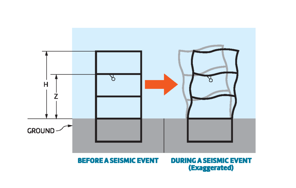
Let’s assume that, from our example that we previously calculated using the table in NFPA 13, we know a little bit more information. We know that the site classification is C – Very Dense Soil and Soft Rock; and we also know that the brace is being installed on the second floor of a four-story building. So the value of Z is 20 feet above the ground and the value of H is 40 feet from the ground. If we plug these values into the formula and leave all the other assumptions in place, we get a Cp value of .343 and a seismic design load of 350 lbs. Now that anchor with a 360 lb. maximum seismic load will work just fine.
This alternate method of calculating Cp, using the same formula as was used by NFPA 13 2016 9.3.5.9.4 to populate their table but with more accurate jobsite specific information, can be very effective in allowing the designer to tailor the seismic calculations to the specific project. It can help to make the bracing system more efficient by allowing maximum spacing, thereby reducing the number of braces installed, thus allowing the use of smaller diameter concrete anchors, lower load seismic components and lower cost brace material. Try it the next time you perform your ZOI calculations and compare where your load is using this method versus the NFPA 13 table. You will be surprised at what a difference you will find and how much you could potentially save.
For more information about this subject, seismic bracing in general, or if would like to see a demonstration of seismic calculation software that allows this approach to calculating the seismic coefficient, please contact your local ASC-ES sales representative.
About the Author | Greg Shaughnessy, ASC-Engineered Solutions
Greg Shaughnessy is Marketing Manager for the Pipe Hanger product line for ASC-Engineered Solutions. An expert in the field of pipe hangers and seismic bracing for fire sprinkler systems, he has over 23 years of experience in the industry.