 Sprinkler Age A Publication of the American Fire Sprinkler Association

A New Scope for Roofs with Slope
Combustible concealed attics have always been a difficult area for the fire sprinkler industry to adequately protect. Adding to this difficulty is the public perception of failure by automatic fire sprinkler systems when a fire burns unchecked through an NFPA 13R, Standard for the Installation of Sprinkler Systems in Low-Rise Residential Occupancies, attic space which has no sprinkler protection within, although the remainder of the building is sprinklered. Even though the systems have done the job they were designed to do, we still have received negative press because they did not do the job that the media expected them to do. We have also felt the brutal hydraulic penalties imposed in these areas per NFPA 13, Standard for the Installation of Sprinkler Systems, while the other areas within the building’s sprinkler system may only require about one-third of the system demand of these areas, causing our riser sizes and our system prices to skyrocket.
It is not without good reason that these areas prove as difficult to deal with as they are. Having sloped ceilings, narrow channels, being located at the highest point of the building, and typically being cold and unconditioned, attics provide a combination of many of the most difficult aspects of fire sprinkler protection. (See Figure 1.) These features cause two increases of 30 percent each in the appropriate sprinkler design area, which ends up being slightly over 2,500ft2. On top of that, the individually allowed square footage spacing per sprinkler drops to 120ft2, which this maximum coverage often cannot even be optimized. This can culminate in design areas requiring approximately 600 gpm for the system demand in a building that would otherwise require less than 200 gpm. As if this wasn’t enough, the fact that these are on top of the building boosts the minimum required pressure to get water to them even further.
With the advent of back-to-back “peak” style attic sprinklers, these huge hydraulic burdens were able to be reduced. These specially listed attic sprinklers are positioned to more effectively take on fires that develop in the attic. They are placed more closely together and are located in the ridge of the roof so that they can achieve a much faster activation. Faster-acting and more efficient sprinklers allow the fire to be attacked before it has as much time to grow and thus allow for a lesser amount of water to be used in fighting it. These systems were able to reduce water usage to 400 and even 300 gpm, a much lesser amount than traditional systems. However, considering that most of the buildings in which these systems are present are otherwise light hazard, there was still room for improvement.
This was the concept on which the Globe Low Demand attic sprinkler scheme utilizing “RE” and “DS” sprinklers was developed, providing an effective attic protection scheme without the additional taxing hydraulic requirement increases. The Globe system further builds on the idea of using the features present in the attic to more quickly and effectively activate sprinklers. At the same time, it makes an effort to get around the biggest weakness of the back-to-back style sprinklers by reducing the distance each individual sprinkler needs to throw and thus reducing the amount of water that each sprinkler needs to use. All of these improvements culminate in providing an attic system typically requiring less than 200 gpm of water.
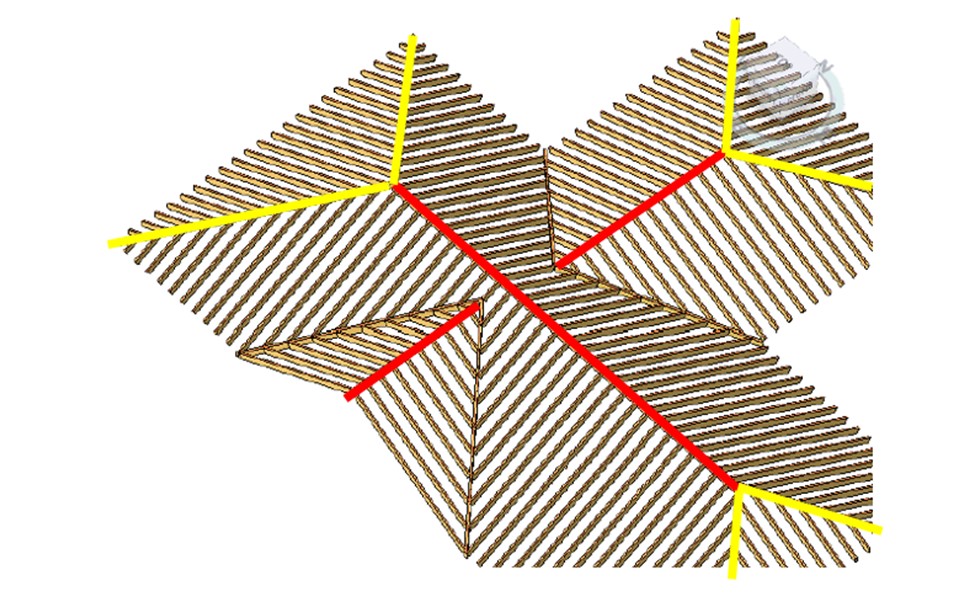
In order to achieve quick activation in any sprinkler system it is important that the sprinklers be placed in the areas where the most heat and smoke will collect. In an attic there are two primary places where this occurs. The first is in the ridge lines; these are the highest points in the attic and thus where all the smoke and heat from a fire will be making their way to. The second is the hip lines. When heat from a fire makes its way up sections of the roof that are connected by a hip line, that heat will end up traveling into and up the hip line before making its way into the ridge line of the roof. The scheme places sprinklers in regard to both the ridgelines and the hip lines to take advantage of the fact that these areas will typically collect heat first. This helps the system to more quickly activate. (See Figure 2.)
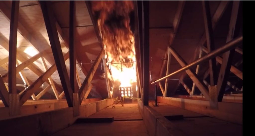
Attic fires don’t always start under areas that are close to a ridgeline or a hip line. When a fire starts in an area that is closer to the eave of an attic, the closely spaced trusses present in attics create an effect called channeling. (See Figure 3.) In this situation the upper members of the trusses cause the majority of the heat and smoke from the fire to stay between the trusses where the fire started. Because of this, the fire will grow much larger before it makes any significant movement perpendicular to the slope of the roof. The best way to fight the fire is again to try and activate sprinklers before it has the chance to grow. To avoid this, the distance between sprinklers perpendicular to the slope of the roof needs to be reduced so that the effects of channeling can be minimized.
Back-to-back “peak” style attic sprinklers address the need to minimize spacing between sprinklers by spacing them closely together along the peak of the attic. This greatly reduces the growth time of the fire before a sprinkler activates; however, it requires the sprinkler to throw water a significant distance to cover its area of protection, which leads to high water demand per sprinkler. The scheme achieves a narrow distance between sprinklers perpendicular to the slope of the ceiling through a different means, that being staggering.
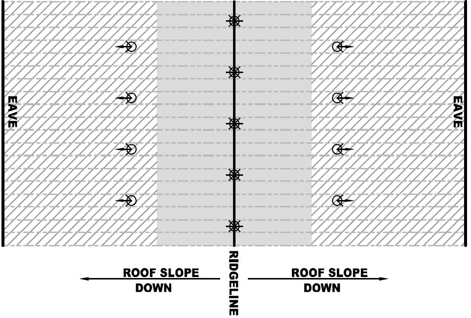
The scheme requires Model RE sprinklers along the peak of the attic spaced six to eight feet on center. It also requires a secondary row of Model DS sprinklers on the slope of each roof four to eight feet on center. The Model DS sprinklers in the secondary rows need to be offset from the location of the Model RE sprinklers at the peak creating a staggered pattern. This allows sprinklers in each individual row to be up to 8-ft apart along the pipe while still maintaining no more than 6 ft between any two sprinklers perpendicular to the slope of the roof. Also, with the roof span being broken up into three sections, each sprinkler has a significantly lowered water demand.
With the staggered design pattern of the scheme, a fire that starts in the eave of the attic will either be quickly met with a Model DS sprinkler on the slope of the roof or by a Model RE as it reaches the peak. In the first situation, water will be directly applied to the fire source by the Model DS, in the second situation the Model RE will provide pre-wetting of the attic as well as assist in pushing heat back down the slope to activate a Model DS. In either scenario the staggering leads to sprinklers being opened and water being applied faster which gives the fire significantly less time to grow. (See Figure 4.)
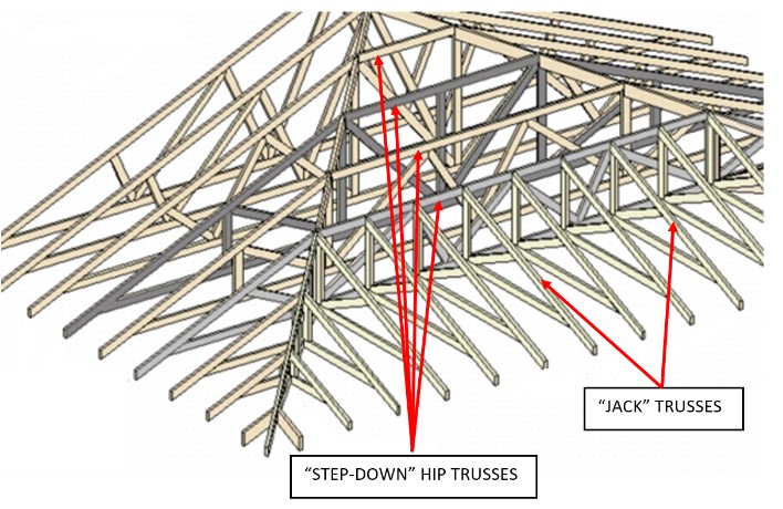
Possibly the most challenging areas to adequately protect in attics are under the hip roof areas. Most hips contain two types of trusses. Typically, “step-down” truss framing is used in the upper portion of hip roofs. “step-down” trusses extend across the hip from the primary slopes on the gabled portion of the attic. This allows for a better support structure for the hip. It also creates truss member channels that are now perpendicular to the slope of the hip and that “step down” along the slope of the hip. These channels and top chord members can now impact the rapid flow of hot gasses up the hip roof to the high point. Additionally, they tend to now allow hot gasses to spread out laterally within the channels as the hot gasses attempt to continue up the slope. Sprinklers in this area of the hip can be placed further apart due to this added lateral gas spread within the channels.
In the lower portion of the hip, typically small truss sections are used to support the hip as it extends to the eave. These small trusses are typically referred to as “Jack trusses” and are positioned parallel to the slope of the hip. (See Figure 5.)
It is important to recognize the use of this common construction method for attic hip roofs and to understand that the fire dynamics can be very different within the upper hip area and the lower hip area. These dynamics have been taken into consideration for laying out and positioning sprinklers as well as with the hydraulic calculations under these hip roofs. For this reason, an “upper hip” calculation and a “lower hip” calculation, at a minimum, is required. While an extra calculation or two may be required, the benefits of performing these simple calculations can be dramatic with regard to improving the required system demand.
This concept of calculating sprinklers based on the shape and structure of the attic framing is no doubt a new concept in attic system design. By looking at attic construction for what it is and addressing these attics for their unique and challenging construction features, we can utilize them to our advantage. By doing so we can avoid imposing layout and hydraulic criteria that simply results in an overload of sprinklers and water to combat the fire. This is what makes the Globe Low Demand scheme both “better fire protection” and economical compared to past schemes.
ABOUT THE AUTHOR: Karl Wiegand, PE works in the technical education department at Globe Fire Sprinkler Corporation where his primary duties consist of providing training, providing technical support and representing Globe’s interests within the fire protection industry. He holds a Professional Engineering license in the field of Fire Protection Engineering and is a graduate of Worcester Polytechnic Institute with a Bachelor of Science degree in Mechanical Engineering and a Master of Science degree in Fire Protection Engineering. Over the last 10 years Wiegand has held positions on NFPA 15, NFPA 24, and NFPA 750. He continues to represent the sprinkler industry on NFPA 16, 101, 820, and 5000 and Underwriters Laboratory’s UL 199 Standards Technical Panel (STP). He can be reached via email at Karl.Wiegand@globesprinkler.com.
IMPORTANT NOTICE: The article and its content is not a Formal Interpretation issued pursuant to NFPA Regulations. Any opinion expressed is the personal opinion of the author and presenter and does not necessarily present the official position of the NFPA and its Technical Committee.