 Sprinkler Age A Publication of the American Fire Sprinkler Association

Look to NFPA Standards for Recommended Practices
Industry and nationwide hydrant flow tests can vary greatly. Most people don’t know the National Fire Protection Association (NFPA) has a “recommended practice” for conducting a flow test: NFPA 291, Recommended Practice for Fire Flow Testing and Marking of Hydrants. The 2017 edition NFPA 25, Standard for the Inspection, Testing, and Maintenance of Water-Based Fire Protection Systems, section A.7.3.1 states “flow test should be conducted in accordance with NFPA 291 for underground and exposed piping flow test.” The 2016 edition of NFPA 13, Standard for the Installation of Sprinkler Systems, section A.24.2.2 in the Testing of Water Supply section also covers the basics of conducting a hydrant flow test but refers to NFPA 291 for specifics. This article will cover the basics of conducting a fire flow test to reduce the chances of a poor result or having to conduct multiple tests, both of which can cause loss of time and money to a project.
Testing for the fire service water supply available from hydrants was first brought up in a 1934 NFPA report and initially adopted as a “recommended practice” in 1935. Then, in 1977, the chapter on flow testing of hydrants was added to NFPA 291. Initially, NFPA 291 covered individual hydrant testing even though NFPA agreed individual hydrant testing does not give complete and satisfactory results. The current editions recommend using “group testing,” or flowing more than one hydrant. Flowing more than one hydrant is not typically necessary, and in some circumstances is problematic in most areas, but using one hydrant for static and residual pressures and a different hydrant for flow is the best practice.
Chapter 4 of NFPA 291, 2016 edition, covers how to conduct a flow test. It recommends having a static, or test, hydrant and one or more “residual,” or flow, hydrants. When determining how many flow hydrants are required, it is recommended by NFPA 291 to flow enough water to provide a minimum 25 percent drop in residual pressure compared to the static pressure. It is important to keep in mind that NFPA 291 is a recommended practice, so unless the local jurisdiction specifically adopts NFPA 291, all the recommendations don’t have to be met exactly.
It is generally accepted that a 25 percent drop is not required for a hydrant flow test to design a fire suppression system. The purpose of a hydrant flow test is to provide information to design a water-based fire suppression system and/or to determine if the water supply meets the firefighting requirements. Since this is the goal of a hydrant flow test, it is best practice today to flow a similar amount of water to the most demanding flow regardless of the pressure. It is impractical in some jurisdictions to get a 25 percent drop in pressure, but the required fire flows are easily achievable. In the end, the results should provide enough information to accurately plot the static and residual points on a water supply graph and show the demands relative to the water supply curve. It is important to keep in mind that most jurisdictions are worried about the flow at 20 psi because the International Fire Code Appendix B as well as NFPA 1, Fire Code, Table 18.4.5.1.2 (2012 edition) have the required fire flows at 20 psi. Because of this, it is best to show the water supply curve at 20 psi to provide the available flow at this point.
Once the hydrants that are to be used for the flow test are determined, a time should be selected which is considered an “ordinary” water demand. An ordinary water demand for residential areas would be sometime between 6:00-9:00 am or 4:00-8:00 pm because this is when most individuals are at home using water. Conversely, sometime between 7:00 am and 6:00 pm would be the best time for testing in an industrial area since this is when most facilities in an industrial area are operating. Also, consideration should be given for traffic issues and potential damage to the area surrounding the flow hydrant due to the water flow.
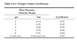
When it comes to which hydrant outlets to use for the flow test, it is better to use the 2½-in. outlets because they are completely filled across the entire cross-section of the outlet versus the pumper outlet (which is anything larger than the 2½-in. outlet) which will have voids, giving inaccurate pressure readings. Make sure to completely open all hydrants to reduce the potential for damage to the hydrant and affect the accuracy of the test results. If it is impractical to use the 2½-in. outlets or it can’t produce the needed flow, the pumper outlet can be used, but the resulting flow has to be modified to account for the voids in the water flow as described in NFPA 291 section 4.8. (See Figure 1.) Also, NFPA 291 recommends keeping the pitot tube pressure readings between 10-30 psi at full flow (the hydrant completely open) for accuracy purposes. If the pitot tube pressures exceed 30 psi it is recommended to open additional hydrants to keep the pitot tube pressures between 10-30 psi. This recommendation is based off of the issues that come with pressures outside of 10-30 psi. When pressures are below 10 psi the results are not as accurate because there is not enough flow to completely fill the cross-section of the open outlet. At pressure above 30 psi several issues arise. The major issue with pressures above 30 psi is positioning the pitot tube properly and holding the position long enough to take an accurate reading of the gauge. Pressures above 30 psi also have the ability to bend and break pitot tube blades. Again, these are all recommendations, and if it is impractical to open multiple hydrants it is best to keep the pressures as close to 30 psi as possible while opening as many hydrants as feasible at full flow. When multiple 2½-in. outlets and hydrants are used to achieve the desired flow, a single pitot reading at each hydrant can be taken and these flows are then added together for total flow at the residual pressure as stated in section 4.10.1.1 of NFPA 291.
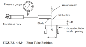
Most people don’t use handheld pitot tubes anymore since there are multiple products on the market that make getting flow pressure reading easier and more accurate. If you use one of these other products, be sure to verify the flows at the different pressure readings since manufacturers have different methods of determining the discharge for their products that are not covered in NFPA 291. Like handheld pitot tubes, other products have recommended pressure-operating ranges as well. For example, Hose Monster has a recommended operating range of 94-321 gpm for their 11/8-in. nozzle, 250-1,000 gpm for their 1¾-in. nozzle and 500-1,432 gpm for their 2-in. nozzle, which are all for use on a 2½-in. hydrant outlet. If you use a handheld pitot tube make sure to hold the blade at a right angle (perpendicular or 90 degrees) to the outlet, so that the orifice of the pitot tube blade is approximately one-half the distance downstream of the outlet and in the center of the flow for the most accurate reading (i.e., 1¼ for a 2½-in. outlet). (See Figure 2 on page 34.) There are several manufacturers that sell blades with notches to help position the pitot tube blades the correct distances from the outlets.
If a pitot tube or other flow pressure reading device is not available, NFPA 291 does give an option for getting the flow reading without one in section 4.9 Determination of Discharge Without a Pitot. NFPA 291 states a hydrant cap can be used on one 2½-in. outlet while opening and flowing the other 2½-in. outlet. According to section 4.9.3 this can be done because the reading should be approximately the same. However, this is to be done only if a pitot tube or other flow pressure reading device is not available or breaks and should not be considered an equivalent option in place of a pitot tube.
When it comes time to read the pressure gauges for the residual and flow pressures, the needle tends to move within a range. This is why gauge selection is important. A gauge that has a maximum pressure of 200 psi should not be used on a pitot tube since we want a reading between 10 psi and 30 psi and a 200-psi gauge would not be able to accurately reflect these values. A gauge with a maximum pressure of 30 psi should not be used for the static/residual pressure since most water supplies have a static pressure above 30 psi. It is best to have a selection of gauges when conducting a hydrant flow test since gauges tend to be more accurate in the middle of their calibrated range. The accuracy is also a percentage of the maximum reading of the gauge so bigger is not better. If there is a selection to choose from then the gauges can be changed to keep the reading within the optimal range. It is also recommended to use digital gauges or liquid-filled analog gauges which reduce the vibrations in the needle, making it easier to read. This is not to say air-filled pressure gauges will not work; it is just easier to use digital or liquid-filled analog gauges. For the most accurate reading from the residual and flow gauges it is best to let the hydrant flow a little while to stabilize the flow before taking a reading. Once the flow has stabilized note the high and low readings of the pressure range on the gauges to determine an average. The average residual and flow pressures are the values that should be used as the results versus the minimum or maximum value.
It is important to properly open and close hydrants, but more specifically dry barrel hydrants. This is a particularly important issue in areas subject to freezing but is an issue for all hydrants. A dry hydrant that is not completely open can flow an excessive amount of water out of the weep hole, causing erosion of the soil around the hydrant base. Over time this can remove enough soil to cause the hydrant to sink and has the potential to damage the underground piping. If a dry hydrant isn’t closed properly, water can be trapped in the barrel and/or cause water to continually flow water out of the weep hole. Water trapped in the dry barrel in areas subject to freezing can cause a large amount of internal damage to the hydrant. The best way to know if the hydrant is completely open is to count the number of complete turns that are made until the operating nut can no longer turn, then backing it off a quarter of a turn. Then, when closing the hydrant, count the amount of complete turns to verify the same number of turns were used until the operating nut can no longer turn compared to opening the hydrant. Once again, the hydrant should be backing off a quarter of a turn. Before the final hydrant cap is reinstalled, verify the water has completely drained out of the dry barrel by feeling for any negative pressure at the outlet. The easiest way to do this is by placing a hand over the open 2½-in. hydrant outlet for few seconds to feel for suction. The first few times there will be an audible pressure release when the hand is removed. Continue to do this until there is no more suction. Then the caps can safely be replaced.
Other information that is important to gather when completing a hydrant flow test is if there are any booster pumps on the water supply, water storage tanks, and the elevation of the hydrants because this could have a large effect on the test results. These effects have a higher residual pressure than the static pressure. Not all water supplies have a linear relationship of flow to pressure. For some water supplies, when the flow demand is increasing, additional water can be provided to an area through multiple pumps and/or valves, causing complex geometries to the pressure and flow relationship at any given point in the system. Although no guidance has been included in NFPA 291 about this, the fact that it is now at least being identified in the annex of NFPA 13 tells us there is hope it will eventually be added to NFPA 291.
Completing a hydrant flow test doesn’t seem that complicated most of the time, but if it is done incorrectly it can end up costing a lot of time and money to a project. For instance, if an initial project flow test is completed at a low-water usage time of the day, the water supply might look great. Then another test is completed a year later at a high-water usage time of day and the results show a pressure drop of 20 psi compared to the previous test. That could be the difference between needing a fire pump and not needing a fire pump. Or, the first flow test is done correctly and it is determined a fire pump is needed. Then another test is done but the test uses the pumper outlet and the tester doesn’t correct for the voids in the stream showing a better water supply, it is hard to explain why a pump is required. Gathering all the right information and trying to follow NFPA 291 may seem tedious, but it could end up saving time, money, and reputations.
 ABOUT THE AUTHOR: Russ Bainbridge, PE, CFPS, MS, is senior fire protection engineer for the American Fire Sprinkler Association (AFSA). He has a bachelor’s degree in fire protection and safety technology with a minor in emergency management from Oklahoma State University and a master’s degree in fire protection engineering from California Polytechnic State University. Bainbridge has Professional Engineer license in Fire Protection Engineering in the state of California. He is a member of NFPA’s Certified Fire Protection Specialist (CFPS) Certificate Advisory Group, sits on the Society of Fire Protection Engineers’ (SFPE) Professional Competency & Credentialing and Nominating Committees.