 Sprinkler Age A Publication of the American Fire Sprinkler Association
All That It Entails
With all that NFPA 25, Standard for the Inspection, Testing, and Maintenance of Water-Based Fire Protection Systems, includes, few things are as straight forward as the trip testing of a dry system valve. Straight forward, however, does not mean uncomplicated. So, don’t lose focus during this test procedure or you’ll find yourself having to perform it all over again to get the information needed for a proper functional test. Of course, that goes for any test where one may think the results are not accurate, but it is one thing to re-perform the testing of a wet system or even a fire pump three-point flow test. It is an entirely different burden to have to drain, reset, and pump up a dry valve in order to retest it a second time. What’s the famous saying? You know it… if you don’t have time to do it right the first go around, where is the time going to come from to do it correctly the second go around?
This article will cover the most important areas on which to focus in the hopes of helping to avoid the costly and time-consuming dry trip retest. Let me start by saying that if you’re reading this article then dry system valve trip testing is probably something with which you are familiar and already understand. With so many variations of dry system valves and set ups, this article is meant to be a refresher or a checklist for you to confirm what you already know; it is not meant to be the “end all be all” to dry system valve trip testing. So, with the disclaimer out of the way, let’s get to it.
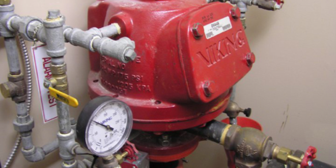
The most important thing to do with a dry system valve is slow down… slow way down. This equipment is touchy and once tripped, leaves no chance to go back and get your previous static pressures (air, water, quick-opening device, etc.). So upon walking up on one, look it over and take some notes. Firstly, notice if there is a quick-opening device (QOD) and what pressure is on it. Also, pay attention to whether there is a low-pressure actuator or a standard actuator and then validate by verifying that the pressure concurs with the system gauge. Keep in mind that the QOD also has to match the actuator as either standard or low-pressure; they don’t mix and match. It is not uncommon to walk up on a dry valve and have the QOD out of service or have a low-pressure actuator with 38 pounds of air or nitrogen on the system. Those low-pressure actuators should have between 13 and 18 pounds of air or nitrogen in them according to the manufacturer, not 38. Additionally, find the air compressor or nitrogen generator and confirm that it is operational before attempting the trip test. If it’s not working, you won’t be able to pressurize the system without repairing the unit or bringing in temporary air or nitrogen to use. Notice the water pressure on the system; is it fed from city pressure or is there a pump supplementing the pressure? All of these things affect the performance and accuracy of the test results. Remember the reason for performing the test – to ensure the functionality of the valve to operate if it is needed. Therefore, the starting parameters need to be accurate in order to ensure the final results are accurate. Finally, pay attention to the temperature. Dry system valves shall be trip tested during the warm seasons when there is time to drain down the piping prior to freezing weather.
After assessing the equipment on the system to be operated and documenting all of the pressures, the technician will need to understand what kind of test is going to be performed. Dry system valve trip testing can be performed as a partial trip test or as a full flow trip test. The full-flow trip test is conducted every third year with the control valve fully open. The water delivery time to the most remote outlet is compared to the system acceptance results. Longer water delivery times could mean the degradation of the system or water supply, resulting in significant delays in system operation. By contrast, a partial trip test is performed the other years with the control valve partially open to prevent the system from filling with water. It does not require water delivery to the most remote outlet. The full-flow test procedure requires two people to perform where the partial trip test procedure can be performed with one technician as long as the control valve is not a wall post indicating valve (WPIV) or a post indicating valve (PIV).
So far there has been a whole lot of looking, assessing, and organizing but we haven’t touched a thing. We’ll perform the procedures for the partial dry trip test first. Let’s assume the customer is expecting you and they have already notified the local fire department, if required, and the monitoring company has the system on test. Before the test is conducted, make sure that the area where water will be discharged can handle the volume and pressure and that it is safe to discharge. Then,
• Record the air or nitrogen pressure on the QOD (if it exists and confirm it matches with the actuator, if one exists) and on the system side of the valve, taking note if a low-pressure or standard actuator is installed.
• Record the water pressure on the supply side of the valve.
Note: At this point, the technician should follow the pre-planned impairment procedures in Chapter 15 to secure the fire pump (if it exists). Technicians should follow their company procedures as they align with NFPA 25.
• Fully open the main drain and flush the water supply. While the main drain is flowing, slowly close down the system control valve until the main drain can no longer provide flow through the entire outlet. Some water needs to be exhausting from the drain; do not close the system control valve tightly.
• Fully close the main drain.
Note: The technician can choose to close the QOD (if it exists) or leave it in service. The QOD has to be tripped quarterly so this may be a good time to perform that test. The technician should follow their company’s procedure whether to perform the QOD trip as part of the dry trip or as a separate test after the dry trip.
• Open a valve on the system to release the air or nitrogen.
• Watch the system air or nitrogen gauge and document the pressure at which the dry valve trips.
• Immediately close tightly the system control valve and fully open the main drain valve.
• Fully close the air or nitrogen supply valve and the QOD supply valve (if it exists).
• Fully open the inspector’s test valve and the auxiliary drain valves on the system to allow them to drain any accumulated condensation.
Note: The location of auxiliary drain valves shall be listed at the riser.
• While resetting the interior seat of the dry valve, clean it and make sure the seat will open fully and latch.
• Confirm that the pressure switch flow alarm and the control valve and low air or nitrogen supervisory signals were received at the fire alarm control panel (FACP).
Note: Make sure the dry valve system is not equipped with a paddle style flow switch and be mindful of the order the switches were received at the FACP. Occasionally, switches have been wired or identified incorrectly.
• Reset the seat of the dry valve system and the QOD (if it exists) and apply priming water to the actuator of a newer valve or to the top of a differential dry valve system.
• Fully close all auxiliary drain valves and the inspector’s test valve.
• Fully open the air or nitrogen supply valve.
Note: The air or nitrogen supply shall be able to restore system air or nitrogen pressure to normal within 30 minutes through the bypass connection. If multiple systems exist, the 30-minute fill requirement is only applicable to one system at a time. Technicians may use a supplemental supply to bring multiple systems to normal pressure but the 30-minute requirement must be confirmed using the installed compressor.
• When system air or nitrogen pressure is restored, open the QOD supply valve (if it exists). Document the air or nitrogen pressure on the system side of the dry valve and on the QOD (if it exists).
Note: Compare the two. They should be very similar.
• With the main drain still open, slowly open the system control valve until water starts to release from the main drain. Continue slowly opening the system control valve until it is fully opened and the main drain is fully flowing. Document your residual pressure.
• Slowly close the main drain fully so as to not cause water hammering. Document your return to static pressure.
Note: The technician may choose to close the main drain after partially opening the system control valve to allow water pressure to build up under the seat. However, the technician will be required to perform a valve status test if it is not performed at the time of setting up the valve as described above.
• Hang the system tag with pertinent information at the dry valve system.
• Return the fire pump (if it exists) to normal operation.
• Reset the fire alarm control panel and confirm its status is normal.
Now, let’s take a look at how the full flow dry trip test compares to the partial trip procedures from above. Keep in mind, for this test there will need to be two people present and the use of radios or communication of some kind will be imperative. Certainly one, but I prefer both technicians to have a stopwatch. If a pump exists and it is remote from the location of the valve or the inspector’s test, then a third person will need to be present in the pump room while the pump is running. We’ll make the usual assumptions that we made above and we’ll start the test procedure at:
• Record the air or nitrogen pressure on the QOD (if it exists and confirm it matches with the actuator, if one exists) and on the system side of the valve, taking note if a low pressure or standard actuator is installed.
• Record the water pressure on the supply side of the valve.
Note: At this point, the technician should follow the pre-planned impairment procedures in Chapter 15 to secure the fire pump (if it exists). Technicians should follow their company procedures as they align with NFPA 25.
• Fully open the main drain and flush the water supply.
• Fully close the main drain slowly.
Note: Restore the pump that was impaired per Chapter 15 to normal operating service at this time. It will be needed for the full-flow dry system valve trip test.
Note: At this point, one technician should be stationed at the most remote inspector’s test valve and the other technician at the riser. When the next step is initiated, both technicians will start their stopwatches in order to time the tripping of the dry system valve and the delivery of a full stream of water at the inspector’s test valve.
• Open the inspector’s test valve on the system to release the air or nitrogen. (Timing begins.)
• Watch the QOD gauge (if it exists) and document the pressure when the QOD (if it exists) trips.
Note: This should happen quickly and will most likely result in the dry system valve tripping instantaneously, so be watching both gauges simultaneously as best you can.
• Watch the system air or nitrogen gauge and document the pressure at which the dry system valve trips.
• Document the time at which the dry system valve trips. Call out to your coworker that the system tripped.
• Document the water pressure at the time the dry system valve tripped.
• Confirm operation of the fire pump (if it exists).
• Close the air or nitrogen supply valve and the QOD supply valve (if it exists).
• When a steady flow of water is reached at the inspector’s test valve, the coworker should stop the timing and call in the time to the technician stationed at the riser.
• Document the time it took for water to reach the inspector’s test valve.
• When a steady stream of clear water is present at the inspector’s test valve, close tightly the system control valve.
• The technician should follow the pre-planned impairment procedures in Chapter 15 to secure the fire pump (if it exists).
• Fully open the inspector’s test valve and the auxiliary drain valves on the system to allow them to drain any accumulated condensation.
Note: The location of auxiliary drain valves shall be listed at the riser.
• While resetting the interior seat of the dry system valve, clean it and confirm it latched in the open position.
Note: The full-flow test shall latch the clapper in the open position.
• Confirm that the pressure switch flow alarm and the control valve, low temperature, and low air or nitrogen supervisory signals were received at the FACP.
Note: Make sure the dry valve system is not equipped with a paddle-style flow switch and be mindful of the order the switches were received at the FACP. Occasionally, switches have been wired or identified incorrectly.
• Reset the seat of the dry system valve and the QOD (if it exists) and apply priming water to the dry system valve.
• Fully close all auxiliary drains and the inspector’s test valve.
• Fully open the air or nitrogen supply valve.
Note: The air or nitrogen supply shall be able to restore system air or nitrogen pressure to normal within 30 minutes through the bypass connection. If multiple systems exist, the 30-minute fill requirement is only applicable to one system at a time. Technicians may use a supplemental supply to bring multiple systems to normal pressure but the 30-minute requirement must be confirmed using the installed compressor.
• When system air or nitrogen pressure is restored, open the QOD supply valve (if it exists). Document the air or nitrogen pressure on the system side of the dry valve and on the QOD (if it exists).
Note: Compare the two. They should be very similar.
• With the main drain still open, slowly open the system control valve until water starts to release from the main drain. Continue slowly opening the system control valve until it is fully opened and the main drain is fully flowing. Document your residual pressure.
• Slowly close the main drain fully so as to not cause water hammering. Document your return to static.
Note: The technician may choose to close the main drain after partially opening the system control valve to allow water pressure to build up under the seat. However, the technician will be required to perform a valve status test if it is not performed at the time of setting up the valve as described above.
• Hang the system tag with pertinent information at the dry valve system.
• Return the fire pump (if it exists) to normal operation.
• Reset the fire alarm control panel and confirm its status is normal.
So, in a nutshell, there you have the basic differences between the partial trip test and the full flow dry system valve trip test. I would be remiss if I didn’t reiterate that there are a multitude of system configurations for which a technician needs to be looking, which was the purpose of my first two paragraphs. Additionally, the air compressor or nitrogen generator maintenance, the heating of the riser room, and the draining of auxiliary drum drips are a continual task of which the owner needs to be aware, especially at the onset of cold weather and during freezing weather. These three topics have enough information to fill their own article which is coming shortly. For now, take your time, be aware of the purpose of the equipment you see, and have good documentation so that you can successfully communicate the accurate results of the testing you just performed. Unlike golf, taking a mulligan on a dry system will cost you, and perhaps your boss, a stroke.
ABOUT THE AUTHOR: Howard Clay is employed by VSC Fire & Security, Inc. in its Inspection Division. He received his B.A. in managerial economics from Hampden-Sydney College. Clay is NICET certified in water-based fire protection systems, fire alarm systems, and fire alarm inspections and testing. He holds state backflow prevention testing licenses in both Virginia and North Carolina and carries the FS-IT-C inspection and testing certification in North Carolina. Clay represents AFSA on the NFPA 25 Committee. He has authored articles for magazines of local organizations and has been asked to speak to local businesses, fire departments, and community associations to help them better understand fire protection. Clay is an instructor for AFSA’s ITM Inspector Development program and is a member of the National Association of Fire Investigators (NAFI) and the International Association of Arson Investigators (IAAI). He can be reached at hgclay@vscfs.com.
IMPORTANT NOTICE: The article and its content is not a Formal Interpretation issued pursuant to NFPA Regulations. Any opinion expressed is the personal opinion of the author and presenter and does not necessarily present the official position of the NFPA and its Technical Committee.