 Sprinkler Age A Publication of the American Fire Sprinkler Association

The State of the Standard
NFPA 14, Standard for the Installation of Standpipe and Hose Systems, has been radically revised since I first came onto the committee in the second half of the 2000 cycle. The 1996 edition contained less than one page of definitions, did not make specific provisions for high-rise buildings, and referred to Class II systems as “… for use primarily by building occupants or by the fire department during initial response,” neither of which was applicable or consistent with what we now take for granted as best practices. A lot has changed since then, in both the language and context of the standard. As challenges amplify in the built environment, such as larger building footprints and unimaginably tall towers, the design of standpipe systems has become – as it should be – more dynamic and performance based. Unlike sprinkler systems that are designed to function autonomously, standpipe systems are a critical part of the human-mechanical interface that characterizes tactical firefighting operations. As such, the design of these systems to serve the specific practices and strategies of its end-users is now a critical part of the basis of that design. As the industries that manufacture firefighting equipment bring new products to market, fire service practices evolve – things we accepted as good practices just 20 years ago are no longer valid in some cases. Many fire departments are turning to higher working pressures; all are using more sophisticated equipment such as variable flow and pressure nozzles. And the standard has changed, maintaining a prescriptive format but now with provisions to adjust designs and performance to suit the responding fire department(s) should it be necessary to do so.
Perhaps the most significant change in the overall tone of the standard has been the inclusion of provisions for higher working pressures. Today, system working pressure is effectively limited only by the materials that one can use to construct a system. Our firm recently designed a 545-ft tall single zone system, using pressure reduction (as required by local policies) at each sprinkler and hose connection requiring regulation. Was this the most cost-effective design option? No, but it most certainly provides the safest, most reliable and most versatile water supply for firefighters that we could provide. That aspect of the standard is critical: more than just gauging the “intent” of NFPA 14, it’s imperative to remember that the water supply in question is going to be the lifeline of men and women who are in dangerous and compromising conditions. If they should determine at the point of attack that they want more (or less) flow and/or pressure, the system must be configured and maintained so that they can adapt the performance of their equipment and tactics to suit those conditions without confusion or complication.
The 2016 edition is the product of modest, evolutionary changes. One of the long-standing deficiencies was a vague prescription to protect standpipes with fire resistive construction that is equal to the stair shaft rating requirements. While the intent was clear regarding vertical piping, there was confusion regarding horizontal piping that was not part of a standpipe as defined. For 2016, Section and Table 6.1.2.2 have been added to more clearly specify the extent and means of protecting piping in buildings of different heights and construction types. Definitions were added for construction types to assure that these were in harmony with the International Building Code. Another confusing requirement that was clarified concerns the requirements (and exceptions to those requirements) for placement of Class I standpipe connections at horizontal exits. To that end, Section 7.3.2.2.1 and Figure A.7.3.2.2.1 have been added, to clarify conditions where additional hose connections at horizontal exits are required or not. The intent is that if areas on one side of a horizontal exit can be completely covered by a hose taken from one or more stairwell standpipes, it is not required to install a Class 1 connection on the opposite site of a horizontal exit. The committee also accepted a proposal to simplify standpipe placement at “breezeway” stairs, as commonly found in open exterior corridors in multi-family housing formats. New Section 7.3.2.5 was added and Figure A.7.3.2.5 illustrates where it is now allowed to place one standpipe in the common corridor/landing between two exit stairs that are not further apart than 75-ft 0-in. As with all of the design and configuration requirements, these should be taken as a show of the committee’s intent to harmonize the standard with the building code and widely accepted good practices, but all are subject to approval by the Authority Having Jurisdiction (AHJ).
Although they’re not new for 2016, attention is called to Sections 7.2.4 and A.7.2.4 and also to Section 7.10.1.2.1.1 and Figure A.7.10.2.1.1, which go back to earlier editions. Section 7.2.4 includes the conditions in which master pressure reducing valves may be used to create lower pressure in separate standpipe zones in lieu of single point pressure reducing valves at each sprinkler and hose connection along a standpipes. This section came into the standard by way of committee reaction to concerns that the practice of using master reducing valves to create zones was becoming more commonplace, but the performance of these valves in the field was inconsistent and entirely dependent on the intensity of inspection, testing and maintenance (ITM) on the systems. To assure functionality to the greatest extent possible, redundancy and accessibility are required in Section 7.2.4, as is the downstream connection point for the fire department connection (FDC). Many listed reducing valves have a strict range of flows to which they are to be applied, so it is also required that the minimum flow rate of the regulators be considered, which may require a smaller second pair of redundant reducing valves to allow for low flows like one or two sprinklers. The foundation for these requirements was that master pressure reducing valves may not be the best solution, but in most cases is the cheapest. This shouldn’t be the overarching criterion, but too often is in our industry; in deference to that reality, the committee codified these additional measures to maintain a high standard of care.
Section 7.10.1.2.1.1 and Figure A.7.10.2.1.1 were added in 2013 to enhance and clarify the intent of existing requirements regarding the number of standpipes to be included in calculations and in determining the maximum flow rate for buildings and specific floors within buildings. Where multiple standpipes in a building terminate at different floors, it is not required that the maximum gross building flow (with allowances for every standpipe up to the limit) be considered on floors where fewer standpipes occur. The classic example is a high-rise tower with two standpipes that rises from a podium base with a total of four or more standpipes. At the highest and most demanding level of the podium, a higher flow rate – up to 1,000 gpm for a sprinklered building – must be proven, but the two-riser tower only requires 750 gpm for its most demanding levels. When a fire pump or set of pumps is being considered for a high-rise water supply, all off these demands should be considered, as it’s required that the entire building be connected to an automatic water supply, even if the podium standpipes are not “high-rise” at their upper-most levels.
Practical Applications
Knowing the content and how to navigate any of the NFPA standards is an important part of what we do in fire protection system design and construction, but with standpipes there is another aspect to the application of the standard that is often overlooked by both industry and fire service: How will this system actually be used in practice? What distinguishes NFPA 14 from other building fire systems standards is that even though it contains design concepts like “automatic” water supplies, it is still and will always be a manually deployed system. Unlike sprinklers, the building owner is not the “end user;” the end-user is the responding fire department, and until the past few cycles the standard wasn’t really addressed that way. NFPA 25, Standard for the Inspection, Testing, and Maintenance of Water-Based Fire Protection Systems, has been revised so that it addresses the building owner, specifically, as the responsible party for ITM. NFPA 14 serves multiple stakeholders: it must address the designer and installer to be sure, but consideration is also given to responders who will use the system. What type of equipment do they carry? What size hoses and tips? What flows and pressures will they require to bring one or more attack lines forward from a fire hose connection? What size and configuration of FDC inlets serve them best? To incorporate these variables into a system, the designer must know or acquire such information from the serving fire department. Surprisingly, many fire prevention officers and plans reviewers aren’t familiar enough with firefighting operations and tactics to inform the industry; this is often the case with civilian and building department employees who have no firefighting experience.
A question was posed on the AFSA SprinklerForum about four years ago regarding A.7.8, which advises the designer and fire department that matching of equipment and FDC inlet pressures are critical to the successful operation of a standpipe system. This has been taken by some to be a recommended practice, but it was only intended to enhance understanding of the operational challenges that may be encountered and to encourage discussion of how to optimize the performance of a standpipe to best suit the serving fire department’s hardware and tactics. That information is or should be known to the fire department but it isn’t reasonable to expect a system designer to be so informed. And it is definitely not the intent of A.7.8 to insert the system designer into the process of programming how a fire department uses their equipment or a particular standpipe system. It underscores the importance of a clear understanding “on both sides of the counter” with regard to local tactics and design criteria; the standard has given the AHJ leeway to make specific, performance-based requirements but relatively few have gone beyond the prescriptive requirements in NFPA 14. And it’s important to note that there are still some departments using standpipes to supply smooth bore nozzles that require much lower working pressures than the variable flow and pressure models. So where is the design criteria based? Generally speaking, it comes from long-used fire service recommended practices and standardized training.
For those interested enough to pursue it, I recommend reading NFPA 13E, Recommended Practice for Fire Department Operations in Properties Protected by Sprinkler and Standpipe Systems, and also the International Fire Service Training Association (IFSTA) Pump Operators Handbook. In NFPA 13E, 2015 edition, Section 6.3.4 states that when pumping to a standpipe connection, the pump operator (presumably the apparatus or company engineer) should consider friction loss in the hose between the pump and the FDC, friction loss in the standpipe system; pressure lost (or gained) to elevation, number and size of attack lines operating from the standpipe, and pressure desired at the nozzles. Since it’s not reasonable to expect that the engineer will know the friction loss in the standpipe or make/ model of various valves and devices through which the fire flow must pass, NFPA 14 now requires an informational sign that is intended to state the required inlet pressure at full demand that is required to achieve the minimum discharge pressure at the most remote hose connections. The IFSTA handbook includes a comprehensive procedure for estimating those losses, but summarizes that the engineer should calculate the pressure at the inlet to be what is required by that hydraulic information sign. It goes on to say that, “If none of this information is available, the general rule of thumb is to discharge 150 psi into the FDC.”
This is why, except on taller buildings where more inlet pressure is required, 150 psi is the fire service standard for residual pressure at the onset of pumping into a standpipe system. (This is also a really good opportunity to push for more proactive improvements on existing systems that may not have signage on the inlets. Although it’s not required by NFPA 25, it’s a really good idea to add a hydraulic information sign if one doesn’t already exist.)
It is the engineer’s job is to know his or her equipment, the specific performance attributes of their rig, friction loss characteristics of different lengths, and diameters of hose at difference flow rates. What we need to do as designers/installers is be diligent in the design of the system, inform the responders of how it’s designed to work by way of signage and configuration, then stay out of the way and let them do their thing. It’s not our job to anticipate the exact positive suction head at a pumper truck or know how many 1.-in. or 1.-in. or 2.-in. attack lines will be used in a fire fight. It’s our job to furnish a system that will deliver adequate fire flow for any eventuality within reason, whatever that may be and it will always be a manual system in that regard.
Performance-Based Design
The first standard for design and installation of standpipe systems was adopted in 1915. For many years, low working pressures were adequate to supply straight stream nozzles and the required discharge pressure for Class 1 hose connections was 65 psi. In 1993, the standard was almost completely reorganized and the minimum discharge pressure increased to 100 psi, pursuant to committee review of fire incident reports and input from the fire service. Initially, the committee felt that 150 psi was the appropriate discharge pressure, based on friction losses through hoses, valves and devices, in order to furnish adequate residual to supply the new generation of selectable flow nozzles that were tested and rated at 100 psi. In hindsight, this was a well-informed target but there was also concern that a bump from 65 to 150 would be so controversial that it would be overturned by an amending motion. 100 psi was approved as a compromise, with the collective assumption that it would be raised again in some future cycle, which obviously never came to pass. Today, the minimum discharge pressure at a Class 1 hose connection, as prescribed in the 2016 edition, is still 100 psi and, depending on the equipment and tactics of the serving fire department, that may or may not be adequate.
In the 2003 cycle, the committee made its first attempt to lift the 350 psi pressure limit on standpipes but that effort began in the Report on Comments (ROC) and was deemed too significant to rush through as a committee comment that would likely be challenged by an amending motion. In 2007, the first revision was incorporated that completely removed the pressure limit in favor of language the capped the working pressure at “that for which the system components are rated.” However, this was overturned by an amending motion and the language of the standard returned to the previous edition’s 350 psi limit. In 2010, in consideration of the need to address taller and taller buildings, the committee added the definition for an express main, which is a vertical pipe supplying one or more upper zones of a standpipe system, but does not supply any portion of a low zone. We then removed the pressure limit from express mains, and left the 350 psi cap in place for standpipes that feed hose connections. These revisions were not challenged and can be found in all editions since and including 2010.
What this enables the designer to do is use a series pump arrangement, or a single pump in combination with pressure reducing valves, to consolidate what was previously required to be vertically staged zones in very tall buildings. It offers the design team and serving fire department options that can be tailored to the specific needs of the responders and to cut down on the number of pumps that might be required in very tall buildings. In the course of researching and self-educating as part of the committee’s work on this issue, I became aware that higher working pressures were not restricted to the demands of tall buildings – there was a movement toward high pressure systems throughout the fire protection and suppression communities. Most of us are aware of the benefits of high pressure (HP) mist systems and the rapid growth in that industry. But fire service is also moving toward higher pressures in suppression operations. A company called HMA Fire Suppression is manufacturing fixed and mobile ultra-high pressure (UHP) equipment for both urban and wildland suppression operations. Their units can deliver water at 1,200 psi and foam/water premix at up to 1,400 psi and the company boasts using only 1/10 the amount of agent required at lower pressures. Akron Brass and Elkhart offer variable flow/pressure/shape nozzles that can use up to 1,200 psi to create effective fog and mist patterns at flows as low as 15 gpm. Key Hose Company manufactures HP double-jacket hose with 800 psi couplings to facilitate HP pumping operations at FDC inlets and small diameter attack lines with HP tips. These are just some of the products that we’re aware of and, as tactical strategies evolve, demand for HP products will increase and the variety of product technologies will grow.
 Fire departments purchase equipment that is specified to perform to their standards and to be compatible with their existing equipment. Once their standard operational tactics are established, it’s a fairly straightforward exercise to design a water supply – or a manual standpipe system to convey a water supply – that is adequate to meet the demand of whatever tactics are deployed. As a designer, I need to know enough about those practices to design a functional system. For example, what is the range of inlet pressures that a fire department is willing to pump on mid-rise standpipe system? I’ve heard of departments that require all standpipes to work with a 150 psi maximum inlet pressure, which is fairly restrictive. Accepted practices and NFPA 13E recommend a range of inlet pressure between 150-200 psi, with the warning in 13E, Section 6.3.4.2 that states “Pump discharge pressure in excess of 200 psi should not be used unless the standpipe system has been designed to withstand higher pressures.” This should not be read as a restriction; it’s cautionary advice to assure that systems are not over-pressurized but it’s incumbent on both stakeholders – designer and fire department – to assess what the maximum inlet pressure will be and that the system components are rated for that. In a mid-rise building that is just less than 75-ft tall, it is conceivable that the required inlet pressure may be higher than 175 psi; universally limiting the pressure in manual standpipe systems doesn’t seem prudent in this day and age. And for high-rise buildings, the 2016 edition of NFPA 14 offers both designer and fire department myriad options for working pressure and configurations of standpipes and zones, which should facilitate a thoughtfully partnered approach to tailor the design to the specifications of the responding agency.
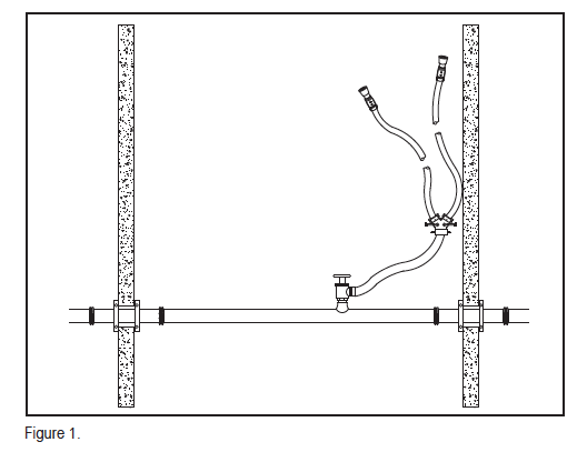
Let’s look at one scenario, as illustrated in Figure 1. We want to calculate adequate residual pressure at the Class 1 hose connection while flowing 250 gpm to feed two attack lines. This illustrates a 2.-in. section of hose connected to a Class 1 standpipe connection with a two-way gated wye at the end, feeding two smaller diameter attack lines with selectable spray/fog nozzles. For this example, we’ll use 1.-in. x 100-ft hose sections (as commonly carried in high-rise hose packs) connected to a 2.-in. x 1.-in. x 1.-in. wye. Let’s say the fire department is using a tip that requires 75 psi such as the Elkhart Phantom, but let’s also compare the required discharge pressure for 50 psi and 100 psi nozzles. Fire hose friction loss tables are widely available – one that’s relatively easy to find and use is on the Elkhart Brass website (it’s in the “Downloads” folder under “Performance Documents”). This simplified chart does not distinguish between different types of hose, but is calibrated for rubber lined synthetic. Countless companies manufacture gated wye housings – Elkhart’s is the model B100, so we’ll use the friction loss values from that one (tech data for these products also available from the manufacturers). It’s a simple calculation to add up the losses of these components:
- 2.-in. hose section @ 250 gpm: 15 psi/100 ft = +/- 1.0 psi
- Gated wye @ 2 x 125 gpm: 250 gpm flow = 18.0 psi
- Attack hose sections @ 125 gpm: 37 psi/100 ft = 37.0 psi
The total loss in hoses and hardware at 250 gpm with two symmetrical streams is 56.0 psi, with a gross demand for this configuration using a 75 psi tip of 131 psi. That’s 31 psi higher than the minimum Class I discharge pressure as prescribed by NFPA 14. For a 50 psi tip, the required discharge pressure is 106 psi; for a 100 psi tip it would be 156 psi. This validates the initial findings and committee proposal from the 1993 cycle, which were rolled back from 150 psi to 100 psi in the ROC phase. The truth is that modern nozzles will generally make workable patterns at more or less than their rated pressures, but regardless of the implied pressure limit (175 psi) of a standpipe system that doesn’t carry hydraulic information signage, fire departments are generally going to pump to the point of attack as needed, and without consideration for whether they’re 10 or 15 or 25 psi over the perceived working pressure of a system. This is why the latest generation of selectable pressure nozzles are so desirable: all of the major manufacturers offer tips that can be adjusted to function at pressures ranging from 45-100 psi.
My role as a system designer is to create a design that affords the highest measures of flexibility, functionality and (most important) firefighter safety that can be reasonably achieved. If you consider the typical manual wet or dry standpipe system, all of the required components – pipe, fittings, valves and inlet connection – can be easily sourced with working pressure ratings in excess of 200 psi. In fact, I can buy listed equipment up to 350 psi without much of a search. I can deliver a truly performance- based standpipe design with relative ease if I know the metrics of the scenario described above.
For the upcoming 2019 cycle, NFPA has an initiative to reorganize and modernize all of the standards. As the new NFPA 14 technical committee chair, this writer will be working with NFPA staff on the exact scope of this exercise in the next few weeks. One thing that we can anticipate is that a performance based approach – or a more flexible standard in that regard – will be prominent in the basis of design for standpipe systems.
 ABOUT THE AUTHOR: Steve Leyton is president of Protection Design and Consulting (PD&C) in San Diego, CA. He began his career in 1981 on the design/build side of the fire sprinkler industry and founded PD&C in 1995 to focus on architectural as well as contractor clients. Leyton’s professional affiliations include NFPA, ICC, AFSA, California Fire Prevention Officers, Northern and Southern Sections, and the San Diego Fire Protection Association. He currently serves as the chairman for the NFPA 14 Technical Committee and as a member of the NFPA 13D/13R Technical Committee. Leyton is also a past member of the NFPA 5000 Technical Committee. He is a past chair of the Installation Committee for the California State Fire Marshal’s 2009 Residential Sprinkler Code Adoption Task Group and a past co-chair of the ICC Ad-Hoc Committee on Residential Fire Sprinklers. Over the course of his career, Leyton has worked on all manner of residential, commercial, industrial, and high-rise projects in the United States, Mexico, and Asia.
IMPORTANT NOTICE: The article and its content is not a Formal Interpretation issued pursuant to NFPA Regulations. Any opinion expressed is the personal opinion of the author and presenter and does not necessarily present the official position of the NFPA and its Technical Committee.