 Sprinkler Age A Publication of the American Fire Sprinkler Association

Part 1: NFPA 13 Requirements
The comedian Bill Engvall made the saying “Here is your sign” well known. When Bill said it, it was directed at someone who just said something that was obvious or just plain stupid. One story I remember Bill telling at a comedy show was about a gentleman who was using a coat hanger trying to unlock his car. Another person walking past looked at the gentleman and asked, “You locked your keys in the car?” The gentleman responded, “No sir, I’m just trying to hang my car up to dry.” Here is your sign.
So, what does this have to do with sprinkler systems? Numerous signs are required by NFPA 13, Standard for the Installation of Sprinkler Systems; however, many sprinkler designers, installers and inspectors are not familiar with the signs they are required to provide. We all know about the requirement for control valve and main drain signs, but what about the rest? This article will discuss the signs that are required, and where appropriate discuss why it is critical that they be provided. All references to NFPA 13 are to the 2016 edition unless stated otherwise.
Let’s start by looking at Table A.6.9. It was developed to make it easier for the user of NFPA 13 to identify what signs are required by the body of the standard. The table is a summary of the signs that need to be provided and it was added to the 2013 edition of NFPA 13. Keep in mind the annex contains material that explains or clarifies the body of the standard but is not legally enforceable.
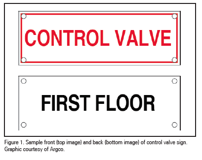
Section 6.6.4 requires all control, drain, venting and test connections be provided with permanently marked weatherproof metal or rigid plastic identification signs. While the general term “drain” is used in the above requirement, I believe that this means the main drain valve assembly. To install drain signs at every nipple and cap or plug that serve as an auxiliary drain seems like an overreach. However, the NFPA 13 installation committee needs to clarify this requirement. The identification signs need to be secured with corrosion-resistant wire or chain. The control valve signs need to identify the portion of the building served. Figure 1 shows the front and back of a typical control valve sign that meets these requirements. Systems that have more than one control valve that must be closed to work on a system or space are required to have a sign referring to the existence and location of the other control valve. Not providing this sign has cost over $500,000 in property damage for one property owner. In an emergency, the control valves were not able to be turned off in a timely manner and no one on-site knew the location of the second control vale. For the record, Table A.6.9 appears to incorrectly reference Section 6.7.4 not Section 6.6.4.
Section 7.6 requires that for all antifreeze systems that are remote from the system riser, a placard must be mounted on the system riser that indicates the number and location of all remote antifreeze systems supplied by that riser. At the antifreeze system’s control valve, a placard needs to placed that indicates the manufacturer type and brand of the antifreeze solution, the concentration by volume of the antifreeze solution used and the volume of antifreeze solution used in the system. Again, it appears Table A.6.9 has an error as it states “Circulating closed loop systems.”
Section 8.16.1.1.8 has a requirement for low point drains that all control valves to be provided with identification signs. This section is not needed since Section 6.6.4 already has this requirement. Hopefully this section can be removed for the 2019 edition of the standard.
Section 8.16.2.3.5.7 has a requirement that most are not aware of. This sign was added for the 2007 edition of NFPA 13 to address concerns that important information about the initial system be posted for future use and reference. Even though this requirement has been in the NFPA 13 since the 2007 edition, I seldom see this sign provided. All auxiliary (low point) drains on dry pipe systems or preaction systems need a sign at the dry pipe or reaction valve indicating the number of low point drains and the location of each individual drain. Lack of providing this sign has caused numerous installing contractors to lose legal claims that were brought against them when systems experienced freeze damage. In one case that I personally know, a maintenance crew drained all the low points that they saw but the system still experienced pipe damaged due to freezing. There were seven low points but two of them were not obvious. The low points were shown on the “as-built” drawings, but because the required signage was not provided, the installing contractor was still found liable. Luckily this claim was small but it could easily have been much different. We have found that providing a 11-in. x 17-in. outline of the system indicating the number and location of the low point drains and the inspector’s test station has satisfied this requirement. We usually install the outline in a picture frame and mount it near the dry or preaction valve. We also include this outline in our Operation and Maintenance Manuals.
Section 8.17.2 has numerous requirements for signage for the fire department connections. Where a fire department connection serves only a portion of a building, a sign needs to be provided indicating the portions of the building served. Each fire department connection needs to be designated by a sign having raised or engraved letters at least 1-in. in height on a plate or fitting reading the type of systems served. If any system served requires 150 PSIG or more, a sign needs to provided indicating the required pressure to be provided.
Section 25.5 requires the Hydraulic Design Information Sign. Like the identification signs required by Section 6.4.4, we all should be familiar with this sign since it has been around for years; longer than I have been in the sprinkler business. However, over the years, a few modifications and new requirements have been added to this sign. The industry used to use the term Hydraulic Data Plate or Placard for this sign. Every hydraulically calculated system is required to have this sign. The installing contractor needs to identify a hydraulically designed sprinkler system with a permanently marked, weatherproof metal or rigid plastic sign secured with corrosion resistant wire or chain. The signs need to be placed at the alarm valve, dry pipe valve, preaction valve, or deluge valve supplying the corresponding hydraulically designed area. Over the last few editions of NFPA 13, additional items were added to the sign. Make sure you are providing all the required information. The sign needs to include the location of the design area or areas, the discharge densities over the design area or areas, the required flow and residual pressure demand at the base of the riser, the occupancy classification or commodity classification and maximum permitted storage height and configuration, the hose stream allowance included in addition to the sprinkler demand, and the name of the installing contractor.
Section 25.6 requires the General Information Sign. This sign was added to the 2007 edition of NFPA 13 to address concerns that important information about the initial system design be posted for future use and reference. Even though this requirement has been in the NFPA 13 since the 2007 edition, seldom do I see this sign provided. The installing contractor needs to provide a general information sign that can be used to determine system design basis and information relevant to the inspection, testing, and maintenance requirements of NFPA 25. The general information sign needs to be provided as a permanently marked, weatherproof metal or rigid plastic sign, which is secured with corrosion-resistant wire or chain. It is required to be placed at each system control riser, antifreeze loop, and auxiliary system control valve. It needs to include the following information: name and location of the facility protected, occupancy classification, commodity classification, presence of high-piled and/or rack storage, maximum height of storage planned, aisle width planned, encapsulation of pallet loads, presence of solid shelving, flow test data, presence of flammable/combustible liquids, presence of hazardous materials, and presence of other special storage.
For Marine systems, Section 26.2.7.5 requires an 18-in. Б~ 18-in. sign displaying the symbol for fire department connection as shown in Table 5.2.1 of NFPA 170, Standard for Fire Safety and Emergency Symbols, to be placed at the connection so that it is in plain sight from the shore access point. I personally think this requirement should also apply to all fire department connections, no matter what the system is serving.
Section A.8.17.1 suggests installing a sign near the local alarm device that is required by 8.17.1. The sign should be located near the device in a conspicuous position and should be worded like: SPRINKLER FIRE ALARM —WHEN BELL RINGS CALL FIRE DEPARTMENT OR POLICE.
While not necessarily classified as a sign, Section 6.2.9.7 requires a list of the sprinklers installed in the property to be posted in the spare sprinkler cabinet. This requirement was added during the 2007 edition of NFPA 13. Are most installing contractors providing this list? I have not seen it. This list needs to include the following information: the Sprinkler Identification Number (SIN) or the manufacturer, model, orifice, deflector type, thermal sensitivity, and pressure rating; general description; quantity of each type to be contained in the cabinet; and issue or revision date of the list.
In summary, the installation of signs is often ignored or thought of as not important. However, the requirement and need for signs is clear. Failure to provide the required signage could put the installing contractor in a liable situation. Additionally, NFPA 25, Standard for the Inspection, Testing, and Maintenance of Water-Based Fire Protection Systems, requires that many of the required signs be checked during the required inspections and if missing, they need to be replaced. Specifically, the Hydraulic Design Information Sign is required to be replaced if missing. This could result in the installing contractor receiving a telephone call asking, “Where is my sign?” from the property owner. For another contractor to develop a Hydraulic Design Information Sign without the benefit of the as-built drawings is not an inexpensive procedure. Bottom line: “Here is your sign!”
About the Author:
John Denhardt, P.E., is quality control manager for Strickland Fire Protection, Forrestville, Md. He has a bachelor of science degree in fire protection engineering from the University of Maryland, holds NICET Level III certificates in automatic sprinkler system layout and inspection & testing of water–based system layout, and is a registered P.E. in numerous states. He is a member of the NFPA 13 Sprinkler Discharge Committee, AFSA, NFPA, and is an SFPE fellow.
IMPORTANT NOTICE: The article and its content is not a Formal Interpretation issued pursuant to NFPA Regulations. Any opinion expressed is the personal opinion of the author and presenter and does not necessarily represent the official position of the NFPA and its Technical Committee.