 Sprinkler Age A Publication of the American Fire Sprinkler Association

What is it?
Exposure protection refers to the protecting of a structure from a nearby fire. This can be in the form of radiation from a nearby fire, exposure to flames from a jetting fire, from a burning building or roof at a lower elevation than the exposed building, or from flying burning debris.1 For the purposes of clarifying terminology, the exposed building is the building that is being protected from fire and the exposing building is the building that is creating a potential fire risk towards the exposed building. This article will address how to determine the required separation distance between an exposed and an exposing building using the method in NFPA 80A, Standard for Recommended Practice for Protection of Buildings from Exterior Fire Exposure. It will also explain some of the basic requirements for laying out an automatic exposure protection sprinkler system.
NFPA 80A states that its purpose is to provide a reasonable degree of protection from exterior fire exposures to give first responders time to mobilize and attack an adjacent fire threat. The simplest way to accomplish this task is to create adequate space between the exposing and exposed structures. NFPA 80A provides the method for determining the required separation based on several factors including construction materials, building height and width, number and size of openings in the walls, and the presence of active fire protection systems.
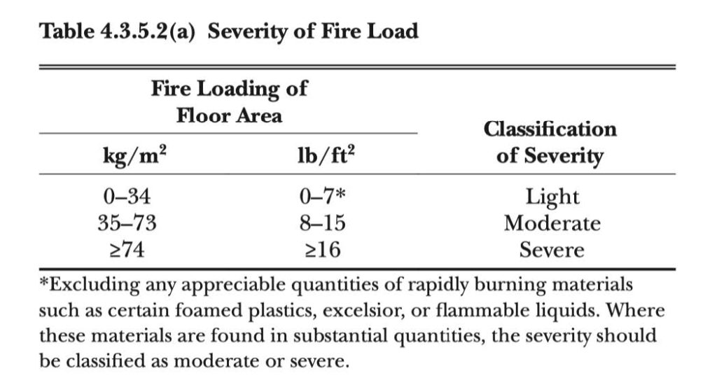
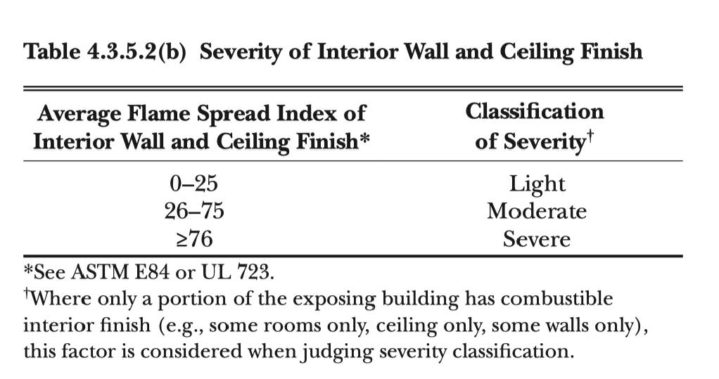
The first step in determining the required separation distance between two buildings is to classify the severity of the exposure. NFPA 80A classifies the potential severity as light, moderate, or severe, based on two factors—the fuel load per floor area (lb/ft2) and the flame spread rating of the exposing building’s interior wall and ceiling finishes as per ASTM E84, Standard Test Method for Surface Burning Characteristics of Building Materials, or UL 723, Standard for Test for Surface Burning Characteristics of Building Materials. (See Figures 1 and 2 below). The standard states that the more severe of these two criteria should always be used in determining the severity classification.
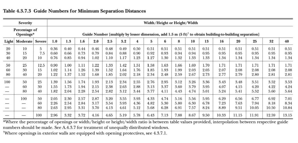
Once the severity has been established, the next step in determining the building separation distance is to determine the width and height of the exposing structure and the percentage of openings on the exposing wall. According to NFPA 80A, 2017 edition, section 4.3.2.1: “The width of the exposing fire should be considered to be the length in feet of the exposing wall between interior fire separations or between exterior end walls where no fire separations exist.” The height of the exposing structure should be the height expected to contribute to the exposing fire. These two dimensions are used to calculate the width/height (w/h) or height/width (h/w) ratio. The larger of the two ratios is used. The percentage of openings is calculated by taking the total surface area of door and window openings on the exposing wall divided by the total surface of the exposing wall and multiplying by 100. The larger of the w/h or h/w ratios, along with the severity and the percentage of openings are applied to Table 4.3.7.3 from NFPA 80A (see Figure 3 below) to figure the Guide Number. The Guide Number is multiplied by the lesser dimension of the width or the height of the exposing wall, and 5 feet is added to the product of those two numbers. This yields the required separation distance.
Now let’s look at a simple example to illustrate. Figure 4 (the featured image at the top of this article) shows a two-story building with an exposing face that is 30-ft tall and 100-ft wide. The first floor has two evenly spaced windows measuring 3-ft wide by 4-ft high and a door that measures 3-ft wide by 7-ft high. The second floor contains three evenly spaced 3-ft by 4-ft windows. There are no internal fire separations. For simplicity, we will assume that the exposing building has a flat, noncombustible roof that will not contribute to the fire. The average fire loading in the building is 7 lb/ft2 (light severity) and the interior wall and ceiling finishes have an average flame spread index of 30 (moderate severity). Since the more severe of these two classifications must be used, the exposing building will be classified as having a moderate severity rating. Assume that the exposed building is of combustible exterior siding and is also two stories, 100-ft wide and 30-ft tall with two evenly spaced rows of three windows measuring 3-ft wide by 4-ft tall. The windows are ordinary single-plate glass windows that project inwards 2 inches from the exterior wall surface. In order to make full use of the property, the builder’s desired building separation is 10 feet.
First: Calculate w/h and h/w for the exposing building.
w = 100 feet h = 30 feet
w/h = 100/30 = 3.33
h/w = 30/100 = 0.30
The larger of these two values must be used, so use w/h = 3.33
Second: Calculate the percentage of openings for the exposing building.
5 windows @ 3 ft x 4 ft = 5 x 3 x 4 = 60 ft2
1 door @ 3 ft x 7 ft = 3 x 7 = 21 ft2
Total area of exposed side = 30 ft x 100 ft = 3000 ft2
Percentage of openings = (60 + 21) / 3000 = 0.027 * 100 = 2.7% openings
Third: Determine the guide number from Figure 3.
Using the percentage of openings value of 2.7 percent and a severity of moderate places us in the first row of numbers in Figure 3. Interpolation between values is allowed when applicable. Moving across to the right on the table to the previously calculated w/h ratio of 3.33 lands between 3.2 and 4. The w/h or h/w numbers are the values across the top of the table that range from 1.0 to 40. Interpolation is allowed here as well. Interpolation for a w/h of 3.33 yields a guide number of 0.492.
Fourth: Calculate the required separation distance.
Multiply the guide number by the smaller of the exposing building’s height or width and add 5 feet.
Solution: (0.49 x 30 ft) + 5 ft = 20 feet of required minimum separation between the exposing and exposed buildings.
The above is a simplified example. There is a more detailed example in Annex B of NFPA 80A if the reader wishes to review a more involved scenario.
If the calculated minimum separation between the two buildings is undesirable, there are several allowances whereby it can be reduced or eliminated. These means are listed in section 5.6 of NFPA 80A. If it can be determined that the exposing building is protected throughout with an approved and properly maintained sprinkler system, then no exposure hazard is considered to exist from the exposing building. Tables 5.6.1(a) through 5.6.1(e) of NFPA 80A provide multiple allowable adjustments in the required separation distance. The appropriate table must be selected based on the construction of the exposed building. Since the exposed building is of combustible exterior construction, refer to Table 5.6.1(a). Since the required separation is 20 ft, a 50 percent reduction in spacing would be needed to accomplish the builder’s goal of a 10-ft separation. Per the table, the installation of an automatic exposure protection sprinkler system over the entire wall, including the glass windows, would allow for a 50 percent reduction in the required spacing.
There are several factors that allow for reductions in the separation distance. These include fire-resistant exposed walls with 3-hour minimum resistance, automatic closers over wall openings with ¾-hour minimum protection, installing automatic sprinkler exposure protection over wall openings, or installing automatic sprinkler exposure protection over the entire exposed wall surface. Depending on which options are chosen and the construction of the exposed walls, the separation may be allowed to be reduced anywhere from 50 percent up to the elimination of the requirement for a separation distance altogether (0-ft separation). In reality, a 0-ft separation may not be allowed due to required property set-backs, fire department access, or local ordinances, so additional research is recommended.
Where automatic sprinkler systems are utilized for exposure protection, NFPA 13, Standard for the Installation of Sprinkler Systems, gives designers some direction for protection of windows, wall surfaces, combustible cornices, and combustible roofs. Exposure protection sprinkler systems must be automatic unless they are constantly attended.
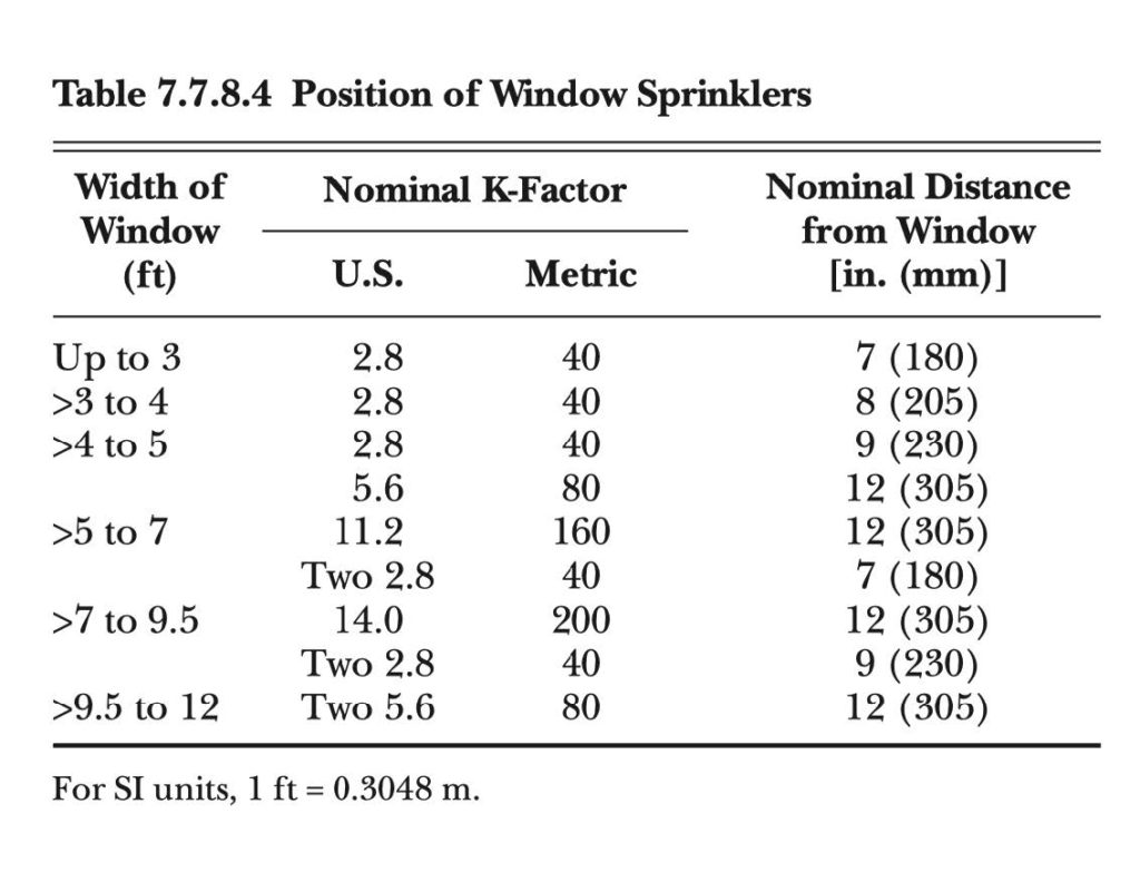
A single row of sprinklers may only protect up to a maximum of two stories or two levels of windows that are aligned vertically. Where windows on a protected wall project inward or outward more than 1 inch, those windows must be protected with a dedicated sprinkler(s). This is because rundown of water on the surface of the wall will be interrupted by the projections, preventing proper coverage of the wall or the window below if only a single sprinkler were utilized. When protecting window openings, listed window sprinklers are required to be used. The window sprinklers must be installed within 2 in. vertically below the window sash and installed horizontally outward from the window surface as required by NFPA 13. (See Figure 5 below.) This same table also dictates the number of sprinklers and minimum K-factor required based on the overall width of the window being protected. Sprinklers used for wall protection must be located 6 to 12 inches horizontally out from the wall and within 6 inches vertically of the top edge of the wall. Horizontal spacing is limited to 8-ft maximum on center.
In Table 23.6.1 of NFPA 13, 2016 edition, Section A lists the required minimum K-factors and minimum densities for window and wall protection. It also gives the number of levels of sprinklers required to be calculated for closed head systems. (See Figure 6 below.) The guide number, as calculated from NFPA 80A, determines this requirement. For open head deluge systems, all heads on a system are required to be calculated.
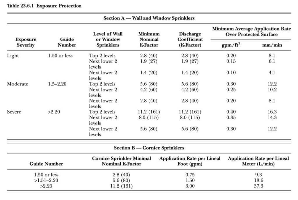
Non-directional spray sprinklers, such as pendents or uprights may be used instead of directional spray nozzles for exposure protection of wall surfaces; however, only half of the discharge from non-directional sprinklers may be credited towards the applied density on the exposed surface. This is because only half of the spray pattern will be delivered onto the wall surface to contribute to the cooling of the exposed surface. The other half of the discharge from the sprinkler will be wasted. As can be seen in Figure 5, the required densities can be quite high for the upper levels for moderate and severe exposures, so care should be exercised in the selection of nozzles and sprinklers. The use of non-directional sprinklers could result in substantial required flow rates from individual sprinklers where 50 percent of the water cannot be counted.
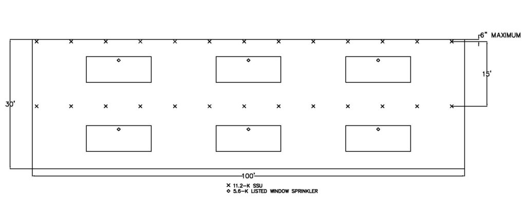
Figure 7 above shows one possible layout for the sprinklers to protect the exposed wall from the above example. To illustrate the point about water wastage from the use of non-directional sprinklers in the paragraph above, standard spray uprights have been selected. A single row of sprinklers could be used in this scenario for wall protection since the building is only two stories in height, but two rows have been shown to reduce the required discharge per sprinkler head. Figure 6 shows that the minimum required density for the top two levels of sprinklers for a moderate severity is 0.3 gpm/ft2 and the minimum K factor is 5.6. The following is the calculation for the require discharge for the sprinklers protecting the wall:
8 ft (horizontal spacing) x 15 (vertical spacing) = 120 ft2
120 ft2 x 0.3 gpm/ft2 = 36 gpm
Since these are standard spray uprights, only 50 percent of the discharge can be applied to the protection of the wall. Therefore, the required discharge must be doubled.
36 gpm per sprinkler x 2 = 72 gpm per sprinkler
So, the required minimum pressure from the 11.2 K upright is:
72 gpm / 11.2K =√(P) P = 41.3 psi
If a directional nozzle had been selected, then the minimum required pressure could have been reduced to 10.3 psi for the same head or to 20.3 psi for an 8.0 K head.
The following calculation is for the window sprinklers:
3 ft x 4 ft = 12 ft2 x 0.3 gpm/ft2 = 3.6 gpm
Since the windows are being protected with a listed window sprinkler, there is no penalty for the use of a non-directional sprinkler head.
3.6 gpm / 5.6K =√(P) P < 1 psi
Because the calculated pressure is less than 7 psi, the minimum required pressure is 7 psi unless the listing of the window sprinkler has a higher minimum required pressure.
NFPA 13 requires that the exposure protection system must have an adequate water supply to allow for the simultaneous operation of all sprinklers on an exposure up to a maximum of 300 horizontal feet of exposure. If the system is an open head deluge system, then the water supply must be capable of supporting the simultaneous full flow of all deluge systems having nozzles within a contiguous 300-ft area of exposure. Depending on the arrangement of the sprinkler system, this could include the flow of sprinklers on adjacent sides of the building. Regardless of the exposure system type, the water supply must be able to meet the required system demand for a 60-minute duration.
When an exposed building employs an exposure protection sprinkler system and the building has combustible cornices, listed cornice sprinklers must also be installed. Cornice sprinklers are required where combustible cornices exceed 12 inches in depth. Cornice sprinklers are calculated similarly to water curtains. Section B in Figure 6 provides the discharge requirements for these sprinklers. Their required application rates are based on a minimum flow per linear foot of cornice as measured along the wall of the exposed surface of the building. The guide number from NFPA 80A also determines the required discharge, as shown in Section B.
Exposure protection sprinkler systems are not widely used in most parts of the country, perhaps in part because fire loss due to external exposure is less common than loss from fires that start inside of a building. In addition, it is a challenge to install an exterior sprinkler system with concealed piping and aesthetically pleasing sprinkler heads. Many building owners and architects will not enthusiastically welcome the added cost and appearance of such devices. However, with the recent fire losses that our country’s West Coast has suffered from wildland fires, both active and passive exposure protection methods are likely to gain popularity in the future.
REFERENCES:
1. Fire Protection Handbook, 20th Edition, NFPA, Quincy, MA, 2008.

ABOUT THE AUTHOR: Parks Moore is chief executive officer of S&S Sprinkler Company, LLC in Mobile, Alabama. He has a bachelor’s degree in mechanical engineering from Vanderbilt University and a master’s degree in business administration from Tulane University. Parks is a licensed fire protection engineer, a Certified Fire Protection Specialist and holds a NICET IV certification in water-based systems layout. He currently serves as an alternate member on the NFPA 13 Technical Committee for Installation, principal member of the NFPA 15 Technical Committee for Water Spray Fixed Systems, and is a former member of the NFPA 13 Technical Committee for Hanging and Bracing. Moore is a past president of the Alabama Fire Sprinkler Association and has been actively involved as one of its board members since 2007. He is a member of AFSA, NFPA, and SFPE.
IMPORTANT NOTICE: The article and its content is not a Formal Interpretation issued pursuant to NFPA Regulations. Any opinion expressed is the personal opinion of the author and presenter and does not necessarily present the official position of the NFPA and its Technical Committee.