 Sprinkler Age A Publication of the American Fire Sprinkler Association

Have You Accounted for Thermal Expansion?
Plastic piping systems are very popular and have undoubtedly been a major factor in the economical installation of sprinkler systems. A common misconception in our industry may be that any system designer who can design a traditional steel-pipe fire system can also design a plastic system. In certain cases, this may be true. However, in order to properly design a plastic-piping system, designers must consider an entirely separate set of design criteria that are often overlooked.
Plastic piping has very different physical and chemical properties than steel pipe. One physical property to consider is the thermal expansion characteristics of plastic piping. According to the Spears CPVC Fire Sprinkler Products Installation Instructions, the coefficient of thermal expansion of FlameGuard piping is 0.000032 in./(in.°F). Other manufacturers state similar numbers. This number may not seem significant; however, the expansion coefficient of steel is much smaller at approximately 0.0000073 in./(in.°F). A little math will show that plastic piping is more than four times as responsive to temperature change than steel pipe. While this drastic difference in thermal expansion between plastic and steel is not specifically stated in the manufacturers’ installation instructions, they do provide guidance regarding this facet of design.
Some installation regions are subject to significant temperature fluctuations throughout the year. A region may experience lows of single-digit temperatures and highs pushing 100°F. Thermal expansion of plastic piping should be carefully considered in these regions.
For example, consider a typical hotel constructed of wood with a rectangular-shaped footprint and a long central hallway. Mechanical equipment will not be located in the hallway ceiling because the HVAC units are located on the exterior walls of each room. Utilizing plastic piping may be a good choice in this situation. (See Figure 1.)
A common approach to sprinklering the building might be to install a main straight down the hallway and run branch lines into each room. Suppose that the system is installed during the colder temperatures while the building is unheated? When the building is later completed, the piping may be subjected to conditioned temperatures of perhaps up to 80°F. The result could be that system piping has been exposed to a temperature range of about 70°F. In this scenario, the expansion and contraction of long main should be considered.
The change in length of the main is calculated as: ∆ L = 12 x e x L x ∆ T
Where: ∆ L = change of length of the pipe in inches, e = 0.000032 (coefficient of linear expansion of the CPVC sprinkler pipe), L = length of run in feet, ∆ T = temperature change in °F.
Referencing Figure 1, the length of run is 165 ft and the change in temperature is 70°F as stated above.
∆ L = 12 x 0.000032 x 165 x 70 or 4.44 in.
The above calculated movement of the piping should be considered unacceptable. At each location a branch line is run into a room in this example the line is extended through a sealed penetration (e.g., fire caulked) in the drywall partition. Essentially, the piping is held rigidly at each of these penetrations. If the designer doesn’t account for thermal expansion, the piping may be subjected to excessive physical stresses at various locations which potentially could have negative consequences. In this example, these stresses can (and should) be avoided by the use of piping offsets or expansion loops. The piping manufacturers’ installation guides should be consulted to determine the best solution.
Another example to consider is a more extreme case of plastic piping utilized on a pier standpipe system (see Figure 2). The argument is not whether this is allowed by NFPA 303, Fire Protection Standard for Marinas and Boatyards, or NFPA 14, Standard for the Installation of Standpipe and Hose Systems. The fact is that many jurisdictions allow (and have allowed) the use of plastic piping for these systems due to the corrosive nature of coastal saltwater environments. In this example, the pier is a 400-ft long straight run of schedule 80 PVC with 21/2-in. hose valves rigidly affixed to the dock at 100-ft intervals. The pier is exposed to the full 100°F temperature extremes of the local climate. The coefficient of thermal expansion of PVC is very similar to CPVC at 0.00003 in./(in./°F).
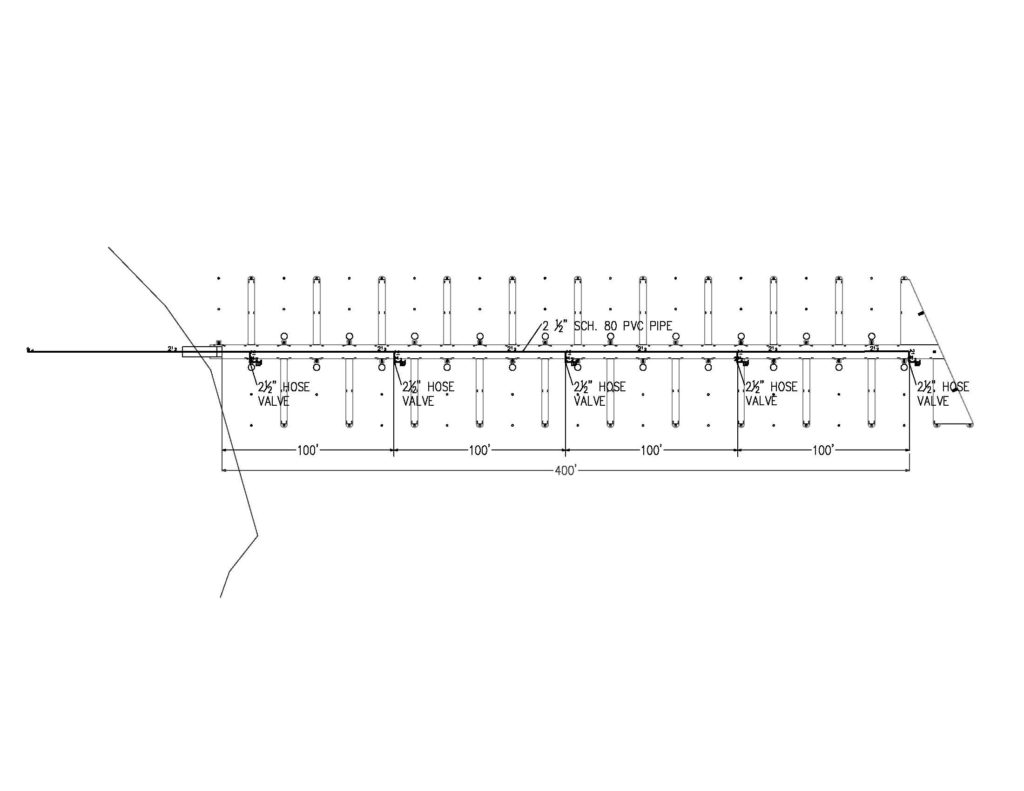
In this case, the expected expansion over the 400-ft piping run is: ∆ L = 12 x e x L x ∆ T or 12 x 0.00003 x 400’ x 100 = 14.4 in.
Clearly, this movement would be unacceptable for many reasons; therefore, the thermal expansion and contraction of the piping must be taken into account. Once again, the piping manufacturers’ technical manual and installation instructions should be referenced for design guidance.
Plastic piping and fittings are great products if used in accordance with the manufacturer’s instructions. Systems containing these products can also be a nightmare for all parties involved if not designed and installed properly. It cannot be stated enough: plastic piping has very different physical and chemical properties than steel pipe. The thermal expansion of plastic piping systems is just one design element of many that should be considered. Other design and installation issues to consider include: proper hanging and clamping, chemical compatibility, appropriate application, listing and approvals, friction loss characteristics, protection from sunlight, handling and storage, painting of piping, etc.
The goal of this article is not to teach design but to simply shed light on possible design considerations. It is our job as an industry to utilize all available information to provide the public with the highest quality and most reliable systems possible. Our designers and installers must be trained and knowledgeable in the nuances of plastic piping systems if we are to utilize these products. System installers are required to be certified and trained by plastic piping manufacturers. These manufacturers have provided detailed guidance regarding the design and installation of their systems. It is up to us to seek out the available information and incorporate these important practices into our work.
ABOUT THE AUTHOR: Daniel J. Mathias, PE, is president of Absolute Fire Protection, Annapolis, Maryland.
IMPORTANT NOTICE: The article and its content is not a Formal Interpretation issued pursuant to NFPA Regulations. Any opinion expressed is the personal opinion of the author and presenter and does not necessarily present the official position of the NFPA and its Technical Committee.